Shane Woody from IST Precision walks us through how a New Way Air Spindle forms the basis for a instrumented spindle designed for metrology applications in the aerospace sector.
Hear directly from Shane Woody, senior engineering manager at IST Precision, as he discusses how they used New Way Air Spindles to develop a custom instrumented spindle for a client.
Introduction
Over the years, IST Precision has developed a wide range of custom motion stages, from ultrasonic piezo stages capable of positioning with atomic precision, to vacuum-based stages, as well as complex electromechanical systems designed for highly specialized life science applications, including cellular and DNA research. Our team has extensive experience in designing mechanical motion stages and custom dimensional inspection gauge heads for a variety of industries.
Most recently, we were tasked with designing an instrumented spindle for a custom metrology machine developed for an aerospace industry client. For this application it was crucial to maintain a sensor’s orientation normal to a surface. The gauge head needed to be compact—weighing no more than a few kilograms—while offering precise rotational control with an accuracy of less than 250 arc seconds with minimal radial and axial error motion. An instrumented spindle offers an effective solution for achieving this level of precision. We define an instrumented spindle as a precision rotary element capable of servo control and capable of transmitting electrical signals through and out of a rotating shaft, energizing a sensing element mounted on the spindle’s rotary head.
In this article, we explore several key design elements that contributed to the creation of this compact, rotary servo-controlled axis. These include
- an air-bearing-based spindle (referred to as an “air spindle”),
- a torque motor,
- an absolute encoder,
- and electrical slip rings.
We will discuss the design and assembly of each of these components in detail.
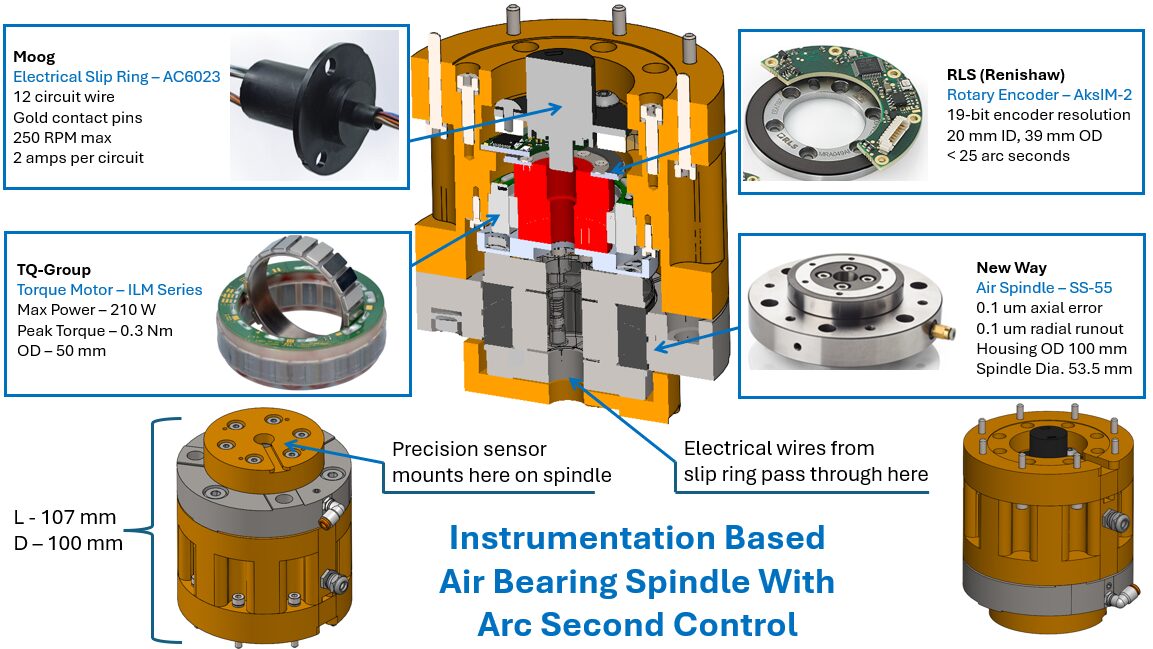
Figure 1: Air Bearing Spindle with Arc Second Control
55mm “T” Series Air Spindle
The porous media rotary bearing is a key component in our design. If the spindle’s rotary axis does not maintain low axial and radial error, it can significantly affect measurement accuracy—especially in precision-based applications that measure in the radial direction at nanometer resolution.
Rotary axis designed from rolling element such as cross roller bearings do not produce nanometer radial error or axial motion. In this application the rotary element must have very low radial error – less than 250 nm. After reviewing multiple vendors and technologies, we ultimately selected the New Way SS-55 Air Spindle due to its compact size and performance specifications.
New Way offers six different air spindle products. The smallest, which met our requirements, was the SS-55 air spindle, shown in Figure 2. This spindle has a total weight of 1.17 kg, with an outer diameter of 100 mm for the fixed frame (stator), a 53.5 mm outer diameter for the rotating element (rotor), and an overall height of 40.3 mm.
This air spindle is based on porous graphite media. Similar to what we described in our article on air bearing goniometers, compressed air is directed into the porous graphite and distributed across precisely engineered surfaces.
Read more here
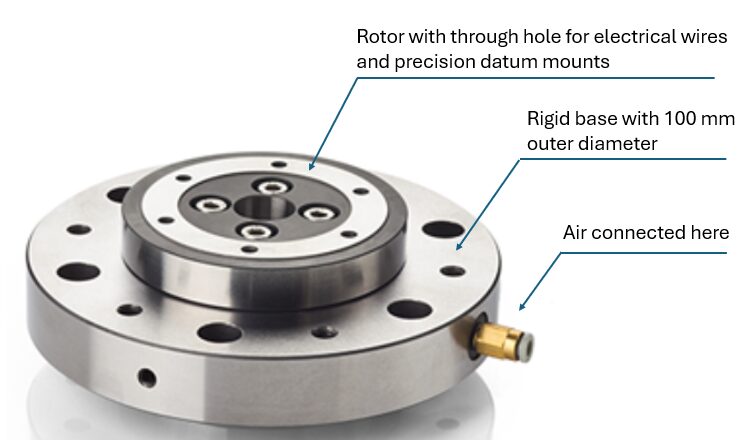
Figure 2: SS-55 Air Spindle
A closer look at the internal structure—shown in Figure 3—reveals a clever design that constrains the rotor both radially and axially. New Way incorporates an inner graphite hollow cylinder with a precision inner diameter (ID) and flat graphite faces on the top and bottom. The top and bottom faces are extremely parallel to each other and highly perpendicular to the inner diameter hole. A short precision shaft is then inserted into the graphite ID and assembled between top and bottom ground faceplates. The result is a very small slip-fit condition between the shaft and the graphite cylinder, with minimal air gap clearance between the faceplates and the graphite surfaces. This design effectively constrains the rotor in both axial and radial directions, whether air is applied or not, acting as both a radial and thrust bearing in one compact unit.
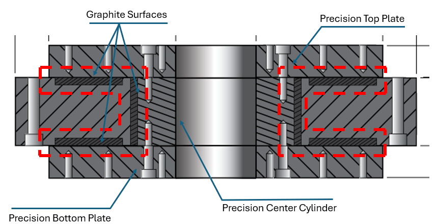
Figure 3: Inner details of the air spindle
Radial and axial stiffness are critical design parameters. This spindle provides 15 N/μm radial stiffness and 20 N/μm axial stiffness. In our application, the instrument was designed to rotate at no more than 200 RPM while carrying a lightweight sensor head with minimal applied forces. As a result, both the radial and axial stiffness values were acceptable for our needs.
Another benefit of using graphite is its resilience in air-off conditions. If the spindle is accidentally energized without air, it can survive short-term operation without immediate damage. This is not the case with other spindle technologies, which may be damaged instantly if operated without air.
Ultimately, the combination of low-error motion, light weight, compact size, and adequate radial stiffness led us to choose this spindle for our application.
The main tradeoff with any air-bearing system is the need for a clean air supply. This must be considered in the design phase. This includes not only supplying air, but also filtering it to remove particulates smaller than 100 nm. In our case, the overall machine already incorporated air bearings elsewhere, and the customer was fully aware that air-bearing technology was the optimal solution.
Frameless Torque Motor
The next essential building block in the construction of an instrumentation spindle is the torque motor. For precision applications, we commonly use a brushless, frameless motor, as shown in Figure 4 below. For this project, we selected a motor from the TQ Group, headquartered in Germany. TQ offers a wide range of motor sizes, including some models smaller than a euro coin, as seen in Figure 4.
The specific motor used in this spindle application is the ILM-E5x14. It features a 50 mm outer diameter stator, a 30 mm hollow shaft diameter for the rotor, and a compact overall length of just 23.2 mm.
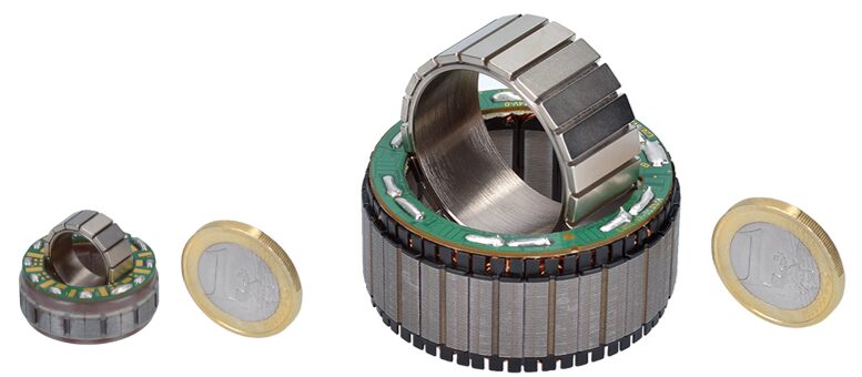
Figure 4: TQ LM series brushless torque motors shown next to euro coins for scale. The motor on the right is the one used in our spindle application.
The ILM-E5x14 offers a very high motor constant of 0.13 Nm/√W, which is approximately three times higher than some competing models—indicating excellent efficiency. It provides a peak torque of 1.72 Nm and a torque constant of 105 mNm/A. The motor can achieve speeds over 7,000 RPM under no-load conditions. However, for our specific application, it is operated at much lower speeds—below 200 RPM. Overall, this motor is an attractive option, offering high torque density with minimal thermal losses.
As we will describe in more detail later, the motor’s stator is integrated into our custom housing, while the rotor is mounted on a custom shaft affixed to the rear side of the air spindle discussed previously. The stator makes direct contact with an aluminum housing to allow for thermal dissipation. Given we have no friction in the bearing and operating at very low RPM speeds our required torque is very low for this application which means the thermal dissipation is also low.
Absolute Encoder
The next key component in the instrumentation spindle is the encoder, which is essential for precisely measuring the rotational position of the spindle. There are two primary types of encoders: incremental and absolute.
- Incremental encoders require a home position sensor to reset the encoder’s position during a power cycle.
- Absolute encoders, on the other hand, do not need a home sensor, as the encoder provides an “absolute” reading of the position, even after power loss. Modern absolute encoders can offer resolutions greater than 19 bits.
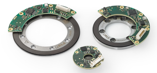
Figure 5: AksIM-2 absolute encoder modules
We have worked with various types of encoders, and one of our preferred choices is RLS, a subsidiary of Renishaw. For this application, we selected the magnetic encoder module series from RLS, Figure 5. This includes both and an electronic module, AksIM-2, and a magnetic encoder ring. The magnetic encoder ring model we are using is the MB039, which features a 39 mm outer diameter (OD) and offers a maximum resolution of 19 bits. Most of the encoder rings in this series achieve an accuracy of better than +/- 100 arc seconds after auto-calibration, with positioning resolution of less than 10 arc seconds. The low profile of the magnetic encoder module was a significant deciding factor for our application, in addition to its resolution. The combined height of both the encoder ring and the electronic module is less than 8 mm, making it an ideal choice for a compact rotary axis design.
Slip Rings
Another key component in this design is the slip ring. For those unfamiliar with these devices, slip rings are used to transfer electrical signals from a stationary set of wires to a rotating set of wires. This is accomplished through a contact brush system, typically coated with a gold alloy for high wear resistance. The electrical signals are transmitted through stationary circuit boards to the brushes, which are in constant contact with a stack of rings, each featuring a shallow groove. The groove design ensures that the brush wires remain in contact with the rings as they rotate. Typically, more than one brush element contacts the same ring to maintain continuous electrical contact, preventing intermittent signals during rotation.
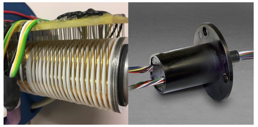
Figure 6: Electrical slip ring images—on the left is a typical internal view of a slip ring, and on the right is the Moog AC6023 model used in this spindle.
Moog offers a wide range of slip ring models, and we selected the AC6023 model, which features 12 circuits. These are used to transmit power to an electrical circuit board located on the instrument. Additionally, electrical signals are transmitted through the spindle to the rotating element, which serves as a reference signal for the application’s sensor element mounted on the spindle. We also need to receive several signals from the rotating head, requiring a total of 10 wires. Thus, the 12-circuit slip ring was the optimal choice for our needs.
The brushes in this slip ring are made from gold for optimal conductivity and durability. The maximum allowable voltage is 240 VAC, and the maximum current per circuit is 2 amps. Importantly, this slip ring has a speed limitation of 250 RPM, which is suitable for our application since the spindle operates at speeds of less than 200 RPM.
Assembly of the Components into the Spindle Housing
The final assembly of the spindle involves carefully integrating all the components discussed earlier into the spindle housing. The main housing is made from aluminum, and is a 100 mm diameter, matching the New Way air spindle diameter. The stator mounts to the aluminum housing and the rotor to mounts onto a custom cylinder, shown in red in Figure 1. To secure the stator in place, we use a thin laser-etched flexure washer that provides preload and holds the stator firmly in the housing, avoiding the need for permanent adhesive bonding. Next, the rotor is bonded to the cylinder, which is then mounted to the air spindle via an adapter plate. During assembly, alignment of the rotor’s central axis with that of the air spindle is critical as these components must be concentric.
Once the two sub-assemblies are complete, the air spindle with the rotor is carefully assembled into the housing. As we install the rotor into the stator, we access the backside to insert shims that ensure the air gap is consistent around the rotor and inside the stator. After ensuring proper alignment, the air spindle is secured to the housing, and the shims are removed. Next, our master technicians route the motor cable through a cable mount that provides strain relief for the cable jacket, attaching it securely to the spindle housing. The individual motor wires are then soldered onto the stator’s circuit board.
Once the motor wires are connected, we proceed with the assembly of the RLS encoder ring. The encoder ring is mechanically attached to the face of the cylinder, ensuring precise alignment. The electronic module is then positioned above the encoder ring at a specified height, as per RLS’ design specifications. We route the Renishaw cable through a machine track (not shown) and provide strain relief using the top mounting plate of the spindle housing. This eliminates the need for a separate strain relief connector.
Finally, the slip ring’s electrical cable bundle is carefully passed through the entire length of the shaft. The base ring of the slip ring is mounted to the housing, and the wires leading out from the slip ring base are securely fastened to prevent any strain on the connections.
The photo below shows the instrumented spindle assembled and mounted onto a large Z-axis machine slideway, figure 7. The New Way 55mm “T” series air spindle air spindle is integrated flush with the main spindle housing. A custom XY adjustment stage, featuring a fine 250-thread-per-inch pitch, is mounted on the rotary spindle to allow precise alignment of the sensor relative to the spindle’s center axis. At the end of the spindle, a custom surface profilometer is installed. This high-precision metrology sensor is capable of measuring surface finish at sub-micron levels. The spindle is specifically designed to maintain the profilometer’s diamond tip normal to the part surface throughout the scan.
The sensor requires electrical power and signal transmission to operate. Electrical signals are used to energize the sensor, with amplifier circuitry boosting the signal before it’s transmitted back through the spindle via slip rings to a remote data acquisition system.
Overall, this design performs exceptionally well in its intended application—a complex surface profilometer system capable of accurately measuring intricate part contours.
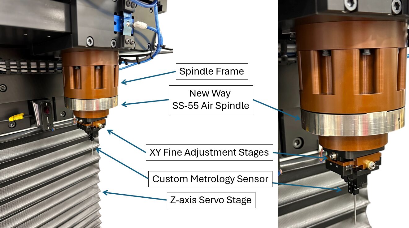
Figure 7: Photo of the air bearing spindle on a metrology machine
Further information about IST Precision and their projects can be found at their website. Additionally, IST and all of our trusted integrators and partners can be found here, listed by specialty and application. If you would like to inquire about a similar product, please contact us!
Learn More About the Porous Media Difference